By continuing to browse this website or by clicking 'I Accept', you agree to the use of cookies. Cookies are stored on your computer or mobile device and enhance your site experience. To learn more about how we use cookies, you can click the 'Learn More' button.
Cathodic Protection Rectifiers, Standard Line, Air Cooled by Universal Rectifiers
Most Popular Conventional Rectifiers. Many Available Options
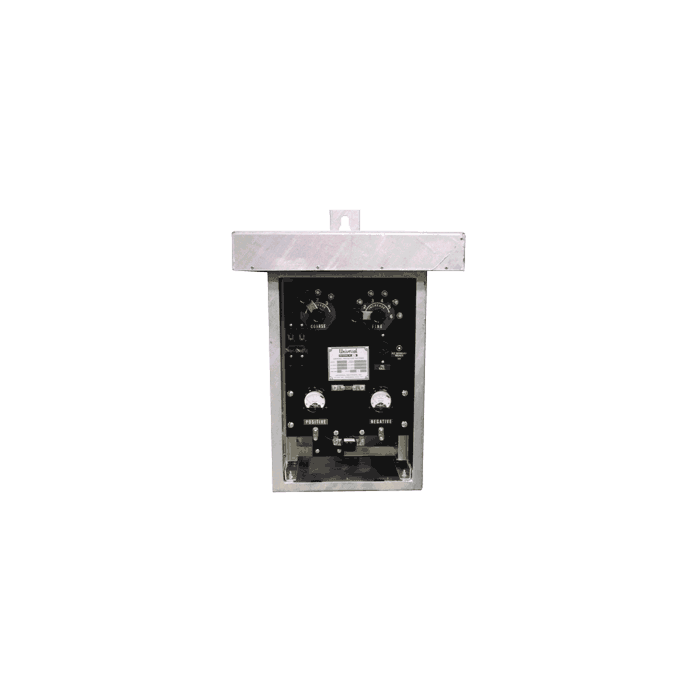
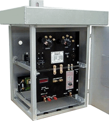
Farwest “Standard Line” air cooled cathodic protection rectifiers, manufactured by Universal Rectifiers, are recognized as industry leading in quality, workmanship and service life. Many years of field-proven service prove their superior design. Conservative equipment ratings, controlled manufacturing techniques, plus many extra features ensure long and trouble-free operation.
Typical cathodic protection applications for the air cooled rectifier line include pipelines, storage tanks, and many other non-hazardous locations where continuous duty, DC cathodic protection power is required.
Heavy duty 11-gauge, hot dip galvanized cabinet with stainless steel hardware
Stainless steel, perforated ventilation screens
Front and side opening doors for easy access and maintenance
Heavy duty, draw-pull, stainless steel cabinet latch
Slide-out equipment racks with separate transformer and stack assemblies for units over 1200 watts
Heavy-duty transformer with 15% over-design for reserve capacity
Standard18-step voltage control link bar taps.
Additional adjustment steps can be custom ordered.
Quick-change, heavy-duty knobs for changing tap link bars
Air Cooled Rectifier Ordering Guide
Configure a model number, like ASAI 20-20 ABCF. Positions from left to right are as follows:
Position #1: Model Type
A = Standard Air Cooled Line
Position #2: Adjustment Type
S = Standard Rectifier (Manual taps) C = Constant Current (Reactor style) D = Constant Current (Solid state) E = Constant Voltage (Solid state)
P = Constant potential (solid state) I = Constant potential IR free (solid state) M = Multiple Modes (Specify Modes Required) V = Variac control
Position #3: Cooling
A = Air Cooled
Position #4: Stack Type
I = Silicon (recommended) E = Selenium (rarely used, selenium stacks age over time)
Position #5: DC Output Voltage Rating
List Maximum DC Voltage Desired (such as 50 for 50 volts)
Position #6: DC Output Amp Rating
List Maximum DC Amperage Desired (such as 25 for 25 amps)
Position #7: AC Input Voltage Rating
AA = 115/230 volts, 1 phase, set for 115 VAC BA = 230/460 volts, 1 phase, set for 230 VAC CA = 230/460 volts, 3 phase, set for 230 VAC EA = 115/460 volts, 1 phase, set for 115 VAC G = 115 volts, 1 phase only H = 230 volts, 1 phase only
AB = 115/230 volts, 1 phase, set for 230 VAC BB = 230/460 volts, 1 phase, set for 460 VAC CB = 230/460 volts, 3 phase, set for 460 VAC EB = 115/460 volts, 1 phase, set for 460 VAC D = 208 volts, 3 phase F = Specify requirements
Position #8: Special Optional Features
C = AC and DC arrestors D = DC arrestor E = AC arrestor F = Filter choke G = Communications filter H = Meter switches I = Base mounting to standard cabinet J = Power "ON" indicator light K = DC failure warning light M = DC breaker (> 100 amps) or fuse N = Powder coated cabinet (hot-dip galvanized is standard on standard air cooled models)
O = Aluminum cabinet option P = Additional voltage control link bar taps R = 115 VAC convenience outlet RR = GFCI 115 VAC outlet (Not available on all models) S = Multiple rectifiers in one case (Advise qty.) T = Anodized aluminum cabinet U = Anodized aluminum cabinet with clear coat W = RMU terminal strip X = Dead front safety panel Y = ETL Certified (Not available on all models) Z = Other, specify requirements
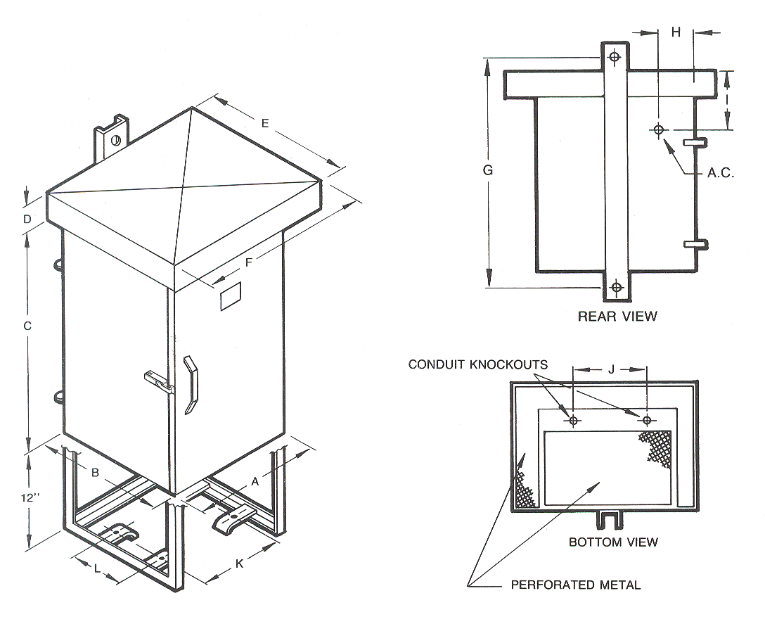
Air-cooled cabinets are available in the following standard size configurations.
Case Dimensions (inches)
Case Size
A
B
C
D
E
F
G
H
I
J
K
L
A
14.5
12
19.5
3
14.5
19
26.25
3
7.5
6
7.5
3
B
17.5
15.5
23.5
3.5
18
23
32
3
9
8
10
6
C
22.5
21.5
23.5
3.5
24
28
32
3
9
10
15
10
D
28.5
22.5
23.5
3.5
25
34
32
3
9
12
21
10
E
34
28
33
5
33
44
41.25
3
18.5
14
25
14
Chassis Dimensions
Rectifier Size
Chassis Width
Chassis Depth
Chassis Height
No. of Chassis
A
11.5"
11.5"
18"
1
B
14.5"
14.5"
10" (20" total)
2*
C
19"
21"
10" (20" total)
2*
D
25.5"
22"
10" (20" total)
2*
The air cooled rectifier cabient size varies with the rectifier output size. To determine the rectifier wattage, multiply the DC output voltage x the output current for.
Example: 50 volts x 50 amps = 2,500 DC watts. Requires a size "B" rectifier cabinet.
Single Phase
Three Phase
Case Size
Maximum DC Watts
Shipping Weight
Maximum DC Watts
Shipping Weight
A
1,200
135 lbs
-
-
B
2,800
185 lbs
1,000
255 lbs
C
6,000
300 lbs
6,500
385 lbs
D
10,000
400 lbs
12,000
625 lbs
E
12,000
525 lbs
18,000
750 lbs
Note: While this chart represents typical cabinet sizes and wattage ratings, adding optional equipment, such as a filter choke, may require that the cabinet size be increased to accept the additional equipment and/or to deal with additional heat generated by the optional equipment.
Farwest “Standard Line” air cooled cathodic protection rectifiers, manufactured by Universal Rectifiers, are recognized as industry leading in quality, workmanship and service life. Many years of field-proven service prove their superior design. Conservative equipment ratings, controlled manufacturing techniques, plus many extra features ensure long and trouble-free operation.
Typical cathodic protection applications for the air cooled rectifier line include pipelines, storage tanks, and many other non-hazardous locations where continuous duty, DC cathodic protection power is required.
Heavy duty 11-gauge, hot dip galvanized cabinet with stainless steel hardware
Stainless steel, perforated ventilation screens
Front and side opening doors for easy access and maintenance
Heavy duty, draw-pull, stainless steel cabinet latch
Slide-out equipment racks with separate transformer and stack assemblies for units over 1200 watts
Heavy-duty transformer with 15% over-design for reserve capacity
Standard18-step voltage control link bar taps.
Additional adjustment steps can be custom ordered.
Quick-change, heavy-duty knobs for changing tap link bars
Air Cooled Rectifier Ordering Guide
Configure a model number, like ASAI 20-20 ABCF. Positions from left to right are as follows:
Position #1: Model Type
A = Standard Air Cooled Line
Position #2: Adjustment Type
S = Standard Rectifier (Manual taps) C = Constant Current (Reactor style) D = Constant Current (Solid state) E = Constant Voltage (Solid state)
P = Constant potential (solid state) I = Constant potential IR free (solid state) M = Multiple Modes (Specify Modes Required) V = Variac control
Position #3: Cooling
A = Air Cooled
Position #4: Stack Type
I = Silicon (recommended) E = Selenium (rarely used, selenium stacks age over time)
Position #5: DC Output Voltage Rating
List Maximum DC Voltage Desired (such as 50 for 50 volts)
Position #6: DC Output Amp Rating
List Maximum DC Amperage Desired (such as 25 for 25 amps)
Position #7: AC Input Voltage Rating
AA = 115/230 volts, 1 phase, set for 115 VAC BA = 230/460 volts, 1 phase, set for 230 VAC CA = 230/460 volts, 3 phase, set for 230 VAC EA = 115/460 volts, 1 phase, set for 115 VAC G = 115 volts, 1 phase only H = 230 volts, 1 phase only
AB = 115/230 volts, 1 phase, set for 230 VAC BB = 230/460 volts, 1 phase, set for 460 VAC CB = 230/460 volts, 3 phase, set for 460 VAC EB = 115/460 volts, 1 phase, set for 460 VAC D = 208 volts, 3 phase F = Specify requirements
Position #8: Special Optional Features
C = AC and DC arrestors D = DC arrestor E = AC arrestor F = Filter choke G = Communications filter H = Meter switches I = Base mounting to standard cabinet J = Power "ON" indicator light K = DC failure warning light M = DC breaker (> 100 amps) or fuse N = Powder coated cabinet (hot-dip galvanized is standard on standard air cooled models)
O = Aluminum cabinet option P = Additional voltage control link bar taps R = 115 VAC convenience outlet RR = GFCI 115 VAC outlet (Not available on all models) S = Multiple rectifiers in one case (Advise qty.) T = Anodized aluminum cabinet U = Anodized aluminum cabinet with clear coat W = RMU terminal strip X = Dead front safety panel Y = ETL Certified (Not available on all models) Z = Other, specify requirements
Air-cooled cabinets are available in the following standard size configurations.
Case Dimensions (inches)
Case Size
A
B
C
D
E
F
G
H
I
J
K
L
A
14.5
12
19.5
3
14.5
19
26.25
3
7.5
6
7.5
3
B
17.5
15.5
23.5
3.5
18
23
32
3
9
8
10
6
C
22.5
21.5
23.5
3.5
24
28
32
3
9
10
15
10
D
28.5
22.5
23.5
3.5
25
34
32
3
9
12
21
10
E
34
28
33
5
33
44
41.25
3
18.5
14
25
14
Chassis Dimensions
Rectifier Size
Chassis Width
Chassis Depth
Chassis Height
No. of Chassis
A
11.5"
11.5"
18"
1
B
14.5"
14.5"
10" (20" total)
2*
C
19"
21"
10" (20" total)
2*
D
25.5"
22"
10" (20" total)
2*
The air cooled rectifier cabient size varies with the rectifier output size. To determine the rectifier wattage, multiply the DC output voltage x the output current for.
Example: 50 volts x 50 amps = 2,500 DC watts. Requires a size "B" rectifier cabinet.
Single Phase
Three Phase
Case Size
Maximum DC Watts
Shipping Weight
Maximum DC Watts
Shipping Weight
A
1,200
135 lbs
-
-
B
2,800
185 lbs
1,000
255 lbs
C
6,000
300 lbs
6,500
385 lbs
D
10,000
400 lbs
12,000
625 lbs
E
12,000
525 lbs
18,000
750 lbs
Note: While this chart represents typical cabinet sizes and wattage ratings, adding optional equipment, such as a filter choke, may require that the cabinet size be increased to accept the additional equipment and/or to deal with additional heat generated by the optional equipment.
Customers Who Viewed This Also Viewed
Are you sure you would like to remove this item from the shopping cart?
This item is a part of the approved quote. Removing it will remove all quote items from the cart.